
Understanding how a residential photovoltaic installation functions can seem intimidating due to the technical jargon of electrical engineering. However, when broken down into logical steps along the path of energy flow, a domestic system follows a straightforward, linear circuit. This comprehensive solar PV wiring diagram UK guide explains every physical component—from rooftop silicon wafers down to your main distribution board—detailing exactly what cable specifications, isolation switches, and safety breakers are required under British electrical standards.
The Complete Energy Flow: From Sunlight to Grid
In a standard British grid-tied solar setup with battery storage, power travels through two distinct electrical zones: the Direct Current (DC) Side (generation and battery storage) and the Alternating Current (AC) Side (household consumption and grid export):
| Circuit Stage | Component Name | Key Function | Primary Cable & Protection Standard |
|---|---|---|---|
| 1. Generation | Solar PV Array (Roof or Ground) | Converts daylight into raw DC electricity | Tier-1 Monocrystalline panels (TOPCon / HJT) |
| 2. DC Isolation | True DC Rotary Isolator | Disconnects live high-voltage DC strings for maintenance | Double-pole, 1000V DC rated (IEC 60947-3) |
| 3. DC Transmission | Solar PV Cable (Positive & Negative) | Carries high-voltage DC to the inverter with minimal drop | 4mm² or 6mm² H1Z2Z2-K double-insulated copper |
| 4. Inversion & Control | Hybrid Solar Inverter | Converts DC to 230V AC and manages battery charging | Compliant with G98/G99 network regulations |
| 5. Storage | LiFePO4 Low/High Voltage Battery | Stores excess solar power for overnight use | Heavy-duty 25mm²–35mm² DC battery cables + 125A fuse |
| 6. AC Generation Isolation | Lockable AC Rotary Isolator | Physical local point of isolation for inverter AC output | Double-pole 230V AC switch (20A–32A rated) |
| 7. Consumer Unit Protection | Dedicated MCB / RCBO in Board | Overcurrent and residual earth leakage protection | Type A RCBO (B20 or B32) on non-RCD split busbar |
| 8. Metering & Grid | Bi-directional Smart Meter (SMETS2) | Measures import and export for smart export tariffs | Monitored for Octopus Agile & Flux export |
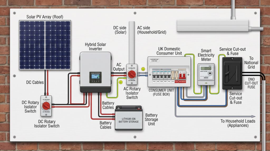
Stage 1: The Solar Array (Roof or Garden Ground Mount)
The system originates at the photovoltaic modules, mounted on roof rails or sturdy aluminium garden frames. Multiple panels are connected in series to create a “string”, where the positive (+) MC4 connector of one panel snaps into the negative (-) connector of the adjacent panel. This series connection sums the voltage while keeping current constant.
- Typical Operating Voltage: A string of 8 to 12 panels produces between 250V and 450V DC under load.
- Where to Source Equipment: UK homeowners and trades typically source Tier-1 panels (such as JA Solar, Longi, or Trina) from reputable electrical distributors like City Electrical Factors (CEF) or specialist renewable suppliers.
Stage 2: DC Cables and High-Voltage DC Rotary Isolator
From the ends of the roof string, a dedicated red (positive) and black (negative) solar cable run begins. These cables must withstand harsh outdoor ultraviolet radiation, extreme frost, and mechanical chafing under roof tiles.
- Cable Specification: Certified UK installations require H1Z2Z2-K harmonised double-insulated 4mm² or 6mm² copper conductors. Understanding when to upsize to 6mm² over long distances is vital to prevent yield loss—detailed in our solar cable sizing guide. Commercial-grade reels are readily available at suppliers like TLC Electrical Distributors and leading outlets on Amazon UK.
- The DC Isolator Switch: Before reaching the inverter, the DC cables must pass through an external double-pole rotary isolator switch (e.g., IMO or Kraus & Naimer). Standard AC switches cannot extinguish high-voltage DC electric arcs; therefore, a switch explicitly rated for 1000V DC (IEC 60947-3) must be utilised. You can inspect suitable isolators directly at Screwfix.
Stage 3: The Hybrid Inverter & Battery Storage Bank
The positive and negative DC conductors enter the Maximum Power Point Tracking (MPPT) inputs of the inverter. In modern installations, a hybrid inverter is preferred because it houses both the solar DC-to-AC power inverter and the bi-directional battery charger within a single enclosed chassis.
- Battery Connections: The battery bank (typically Lithium Iron Phosphate / LiFePO4 chemistry) connects directly to the inverter’s dedicated battery terminals using high-current, flexible 25mm² or 35mm² tri-rated copper cables.
- Battery Overcurrent Protection: A heavy-duty DC isolator and an inline 100A or 125A mega fuse or NH00 fused disconnect switch must sit between the battery cells and the inverter to protect against short circuits.
- Sizing Considerations: For guidance on choosing inverter capacity and expected operational life, consult our detailed breakdown on solar inverter lifespan and replacement. Complete plug-and-play domestic battery setups are widely distributed across the UK via Bimson Power and electrical wholesalers.
Stage 4: AC Isolation and Consumer Unit (Fuse Box) Connection
Once the inverter synthesises clean 230V alternating current, the electricity must safely interface with your home’s existing electrical wiring board:
- AC Rotary Isolator: Mounted within sight of the inverter, a red-and-yellow lockable double-pole AC rotary isolator (rated 20A to 32A) allows utility workers or emergency services to disconnect the inverter from the household mains instantly. Suitable surface-mount AC isolators can be sourced from Toolstation.
- The AC Interconnect Cable: A 3-core 4mm² or 6mm² steel wire armoured (SWA) or heavy-duty Twin & Earth (6242Y) cable runs from the AC isolator directly back to the main consumer unit.
- The Overcurrent Device (MCB / RCBO): Inside the consumer unit, the solar circuit must never be wired into a standard shared lighting or socket ring. It requires its own dedicated Type B or Type C 20A/32A RCBO (Residual Current Breaker with Overcurrent Protection), ideally Type A sensitive to tolerate smooth DC leakage currents, fully conforming to IET BS 7671 18th Edition regulations.
Stage 5: Bi-Directional Meter and National Grid Export
When your solar panels generate more energy than the household loads and battery bank can absorb, the surplus power flows backwards through the consumer unit, passes the main 100A service cut-out fuse, and registers on your electricity supplier’s smart meter (SMETS2). This exported electricity earns revenue via the Smart Export Guarantee (SEG) or high-value flexible tariffs.
Before commissioning any system capable of exporting power, ensure your installer submits formal documentation to your regional network under standard G98 connect and notify regulations, and verify that your installation is declared to prevent any issues with your UK home buildings insurance.